Find the required turns according to stator and rotor dimensions
Operation
Knowing the stator dimensions you can calculate turns based on RPM, voltage and power
Choose the number of turns corresponding to the maximum B value, if the motor allows it.
Divide the chosen value by {slotsInput} (the slots) to get the turns per coil in a single-layer winding; in double layer, half of that
What it is for
It calculates how many turns a three-phase induction motor needs from the dimensions of its lamination stack. It is useful when a stator arrives with no winding or no data from the original. It does not give a single figure but a curve: each possible flux density gives a different number of turns, and you choose according to what the iron can take and the power you are after.
How to use it
Log in with an account whose email is confirmed. The free plan goes up to 36 slots and 4 poles.
Measure the clean stator and enter the data in centimetres: stack length, rotor diameter, tooth width and yoke thickness.
Enter the poles, the slots, the star voltage and the frequency, which is 50 Hz by default.
Press Calculate and read the two charts.
Choose a flux density, take its turns value and divide it by the number of slots.
The input data
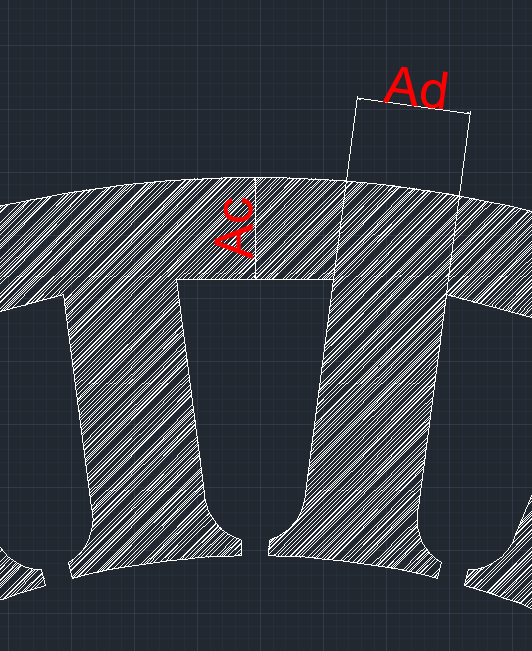
Ad is the tooth width. Ac is the yoke: the iron between the bottom of the slot and the outside of the lamination.
Star voltage: the line voltage if the motor runs in star. If it runs in delta, multiply it by 1.73: a 400 V delta motor is calculated with 690 V.
Frequency: 50 Hz by default. At another frequency, the turns change in inverse proportion: n₁ · 50 = n₂ · f₂.
Poles: 2 poles are about 3000 rpm at 50 Hz; 4 poles, 1500; 6 poles, 1000; and 8 poles, 750.
Length and diameter: the length of the lamination stack, without the coil ends, and the diameter of the rotor or of the stator bore.
Power: your reference to compare with the kW curve. It does not change the number of turns.
How to read the result
The first chart gives, for each flux density in gauss (10,000 G = 1 T), the turns and the power the motor can take. The second gives the resulting flux density in the tooth and in the yoke. The turns value on the chart is the total number of conductors in all the slots, which is why you divide it by Z to get turns per coil.
\[ \text{turns per coil (single layer)} = \frac{\text{result}}{Z} \]
In double layer each slot holds two coil sides, so it is half of that. Higher flux density means fewer turns and thicker wire, and the motor gives more power, but the iron is more heavily loaded and the no-load current rises. Choose the highest flux density that the tooth and yoke allow and that gives the power you need.
Example
A 400 V star motor with 4 poles, 36 slots, 10 cm length and 12 cm diameter:
B (G)
Result
Turns per coil, 1 layer
Turns per coil, 2 layers
7000
1476
41
21
8000
1289
36
18
9000
1144
32
16
10000
1027
29
14
At 9000 G you would get 32 turns per coil in single layer. That is about 192 turns per phase, because a single layer has 6 coils per phase. It agrees with the formula in the turns calculation guide.
Limits and checks
This is an approximate calculation. At the same voltage, the turns are inversely proportional to the frequency and the power directly proportional: at 60 Hz you get 5/6 of the turns and 6/5 of the kW at 50 Hz. The flux densities do not change, because the flux is the same. Far from 50-60 Hz, iron losses rise and that power is optimistic.
As a general reference, about 16,000-18,000 G in the tooth and 13,000-16,000 G in the yoke are usually accepted. Each manufacturer has its own criteria.
If you know the original winding, it takes priority over this calculation. Always compare before winding.
Check that the wire fits with Turns by slot, and start the motor with no load the first time, measuring all three currents.

 Español
 Français
 Português
 Deutsch
 Italiano
 Polski
 Türkçe